General Thoughts and Material List
The belt sander is the number one most important tool for making saleable knives. This by no means implies that you can’t build very high quality knives using only hand tools. I did that for many years. And by knowing exactly what I put into the blade in regards to heat treating, I can positively say that my blades are very good.
Alas, saying that, there is one big drawback for using hand tools only. Most of the people that show an interest in the subject of knives are purchasing them for a collection and not as a working tool. That is fine, but as they buy it for display, the knife needs to be of a higher visual quality. I am not saying that connoisseurs out there are not looking for other qualities, things like materials, construction method, heat treatment method and alike. But I think the majority of knife enthusiasts (at least where I live in, the UK) are looking first of all for a good visual appearance.
So by using hand tools only, you can never (or at least it will take you forever producing a knife) build a knife that is one hundred percent symmetrical and looks immaculate and shiny with crisp lines. Also you will find that to make the knife’s ricasso area completely flat is very, and I mean very, difficult, and this is such a crucial area of the knife.
Selling knives without a belt sander can never really be turned into a long-term viable operation.
I decided to get one. I had been looking on the Internet to buy one, but in the UK it is a very difficult item to find, and if you do find it, it’s very expensive (I bet this is the case everywhere).
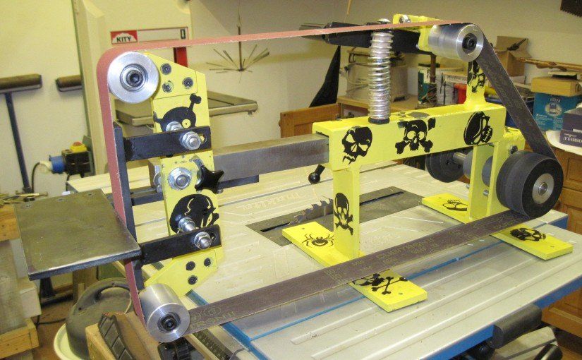
So I went about building my own. I did a lot of online searching and found a few plans for building a belt sander. The KMG type is one of the more simple models. Although it’s simple, it is a very nice entry level belt sander. It is versatile enough to accommodate several attachment heads and it is not so sophisticated that it is complicated to construct.
I did not find however a good enough blueprint for construction, so I drew my own one. It is based on instructions I found on one of the British knives forums.
I have now got it in DWG and PDF format and I will be happy to share it, and In the next few posts I will go about explaining how I built my KMG belt sander.
Here is what you need:
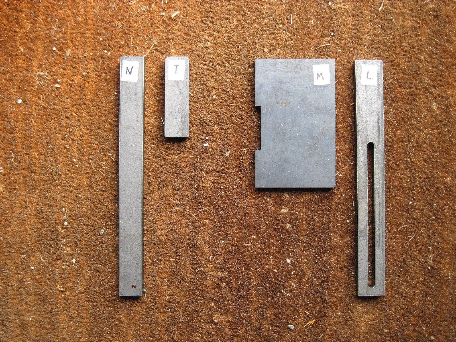
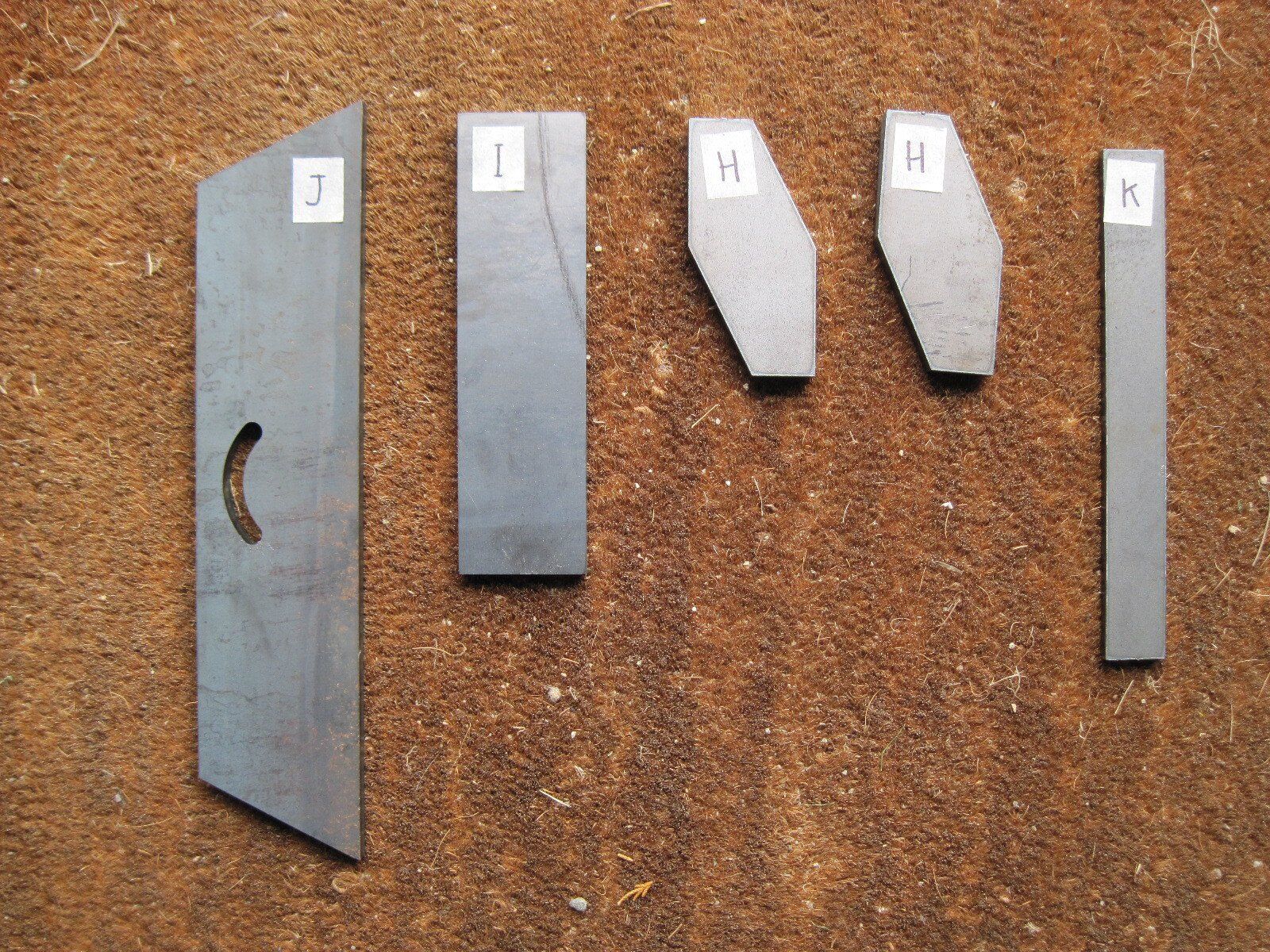
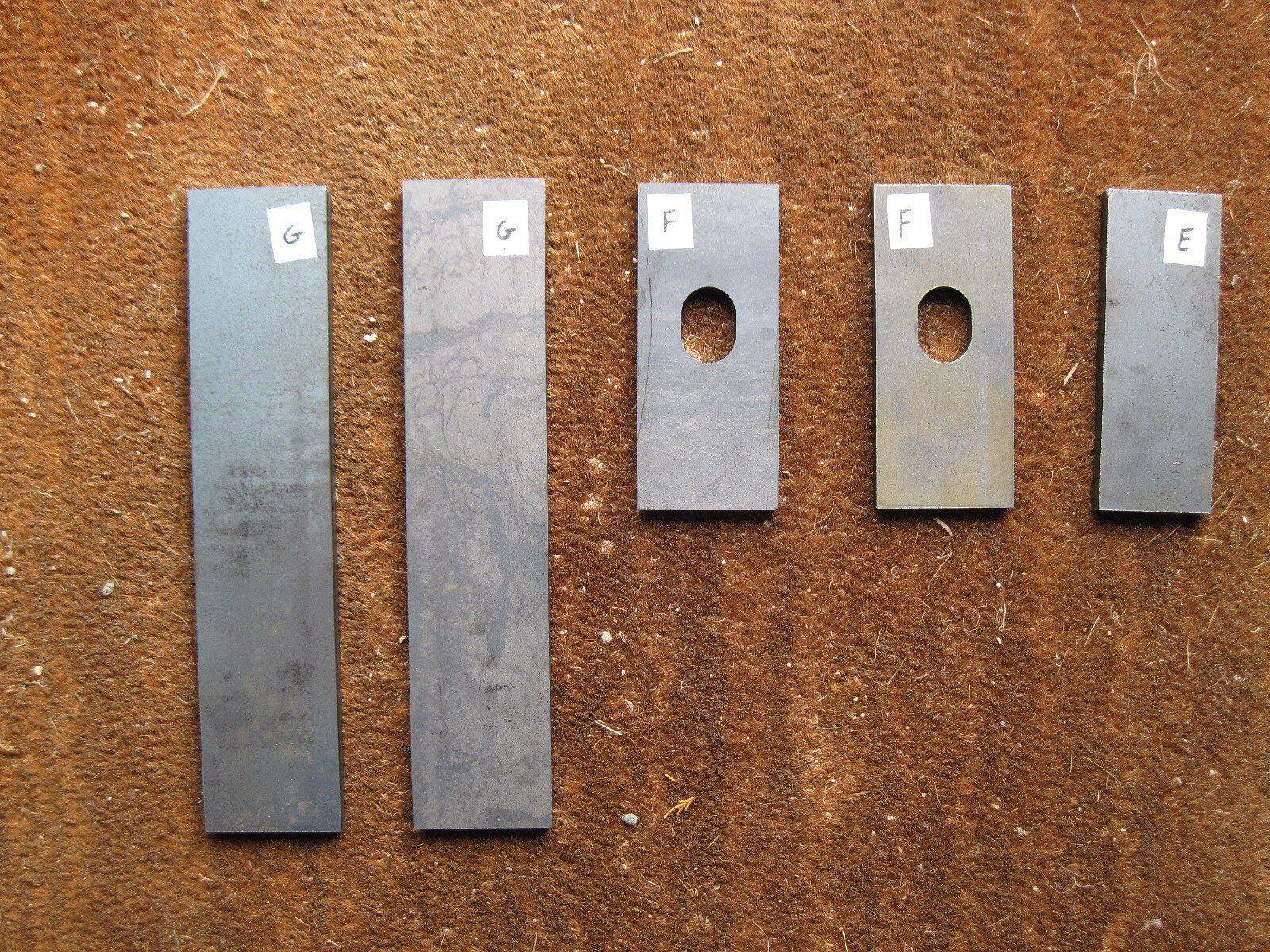
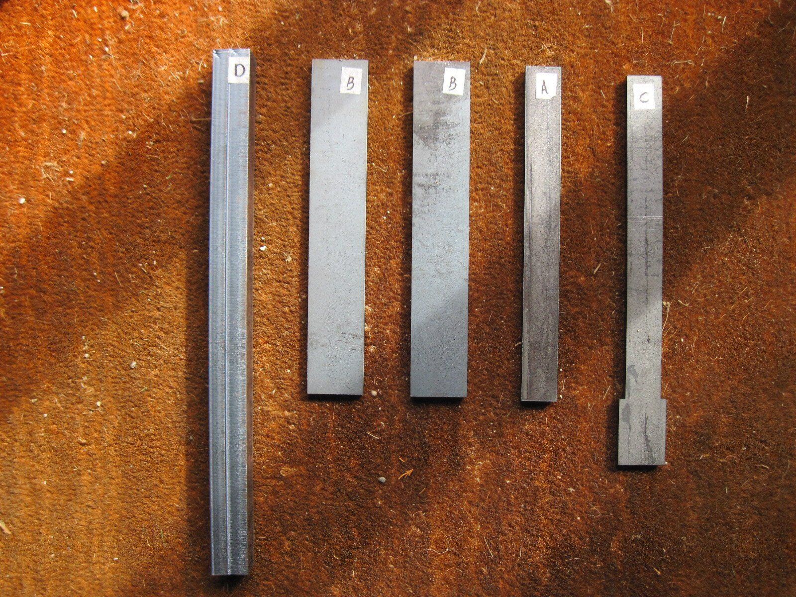
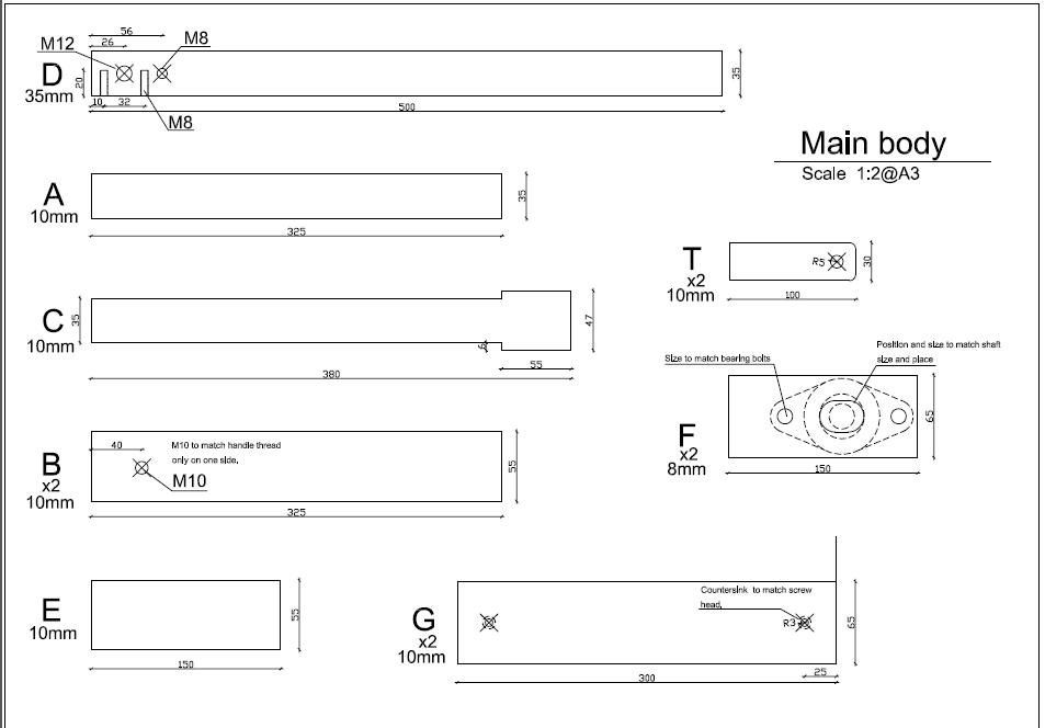
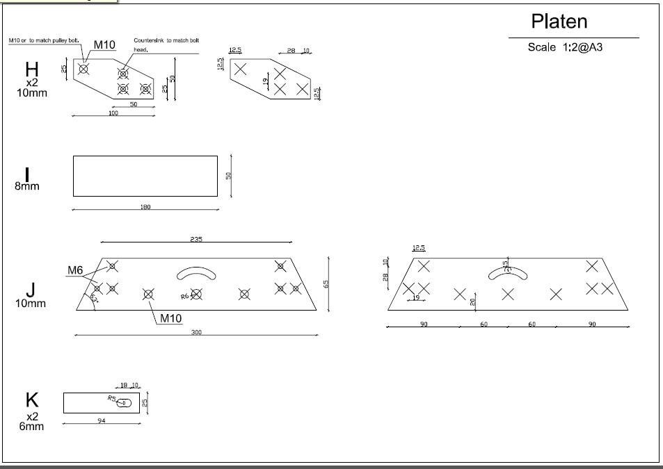
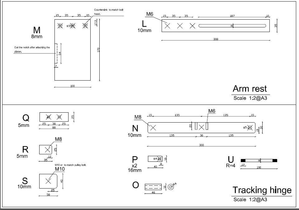
I decided to cut all the part using laser cutting service. It is by far more accurate and fast then what you can achieved cutting it yourself.
If you send it for laser cutting, asked them to hatched the exact location of all the halls you will have, it will save you hell of a lot of time. Also I recommend to asked them to make all the halls that you need to thread, especially those for the pulleys, as they need to be dead striate.
You will also need:
Drive wheels: 100mm diameter x 55 wide with 20mm bore.
2x Platen rollers: Billet aluminium, 50mm diameter x 55mm wide, fitted with 10m ID bearings.
Tracking Pulleys: Billet aluminium, 50mm diameter x 55mm wide, crowned and fitted with 10mm ID bearings.
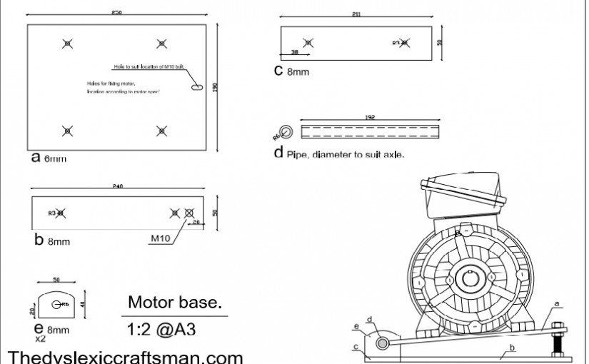
20mm Shaft: In suitable length. See assembly drawings in next post.
2x UCFL.204 bearing: UCFL.204 metric bolt oval cast iron flange housing with 20mm bore insert. Make sure the total width of the bearing can fit in between parts F.
2x V Pulley: 100mm dia.
V belt: To match the pulley. See (or wait for) post part 6.
2x Taper bush: One to fit 20mm shaft and one to fit the motor shaft (presumably 24mm).
One pulley bush lock: For locking the pulley in to the shaft.
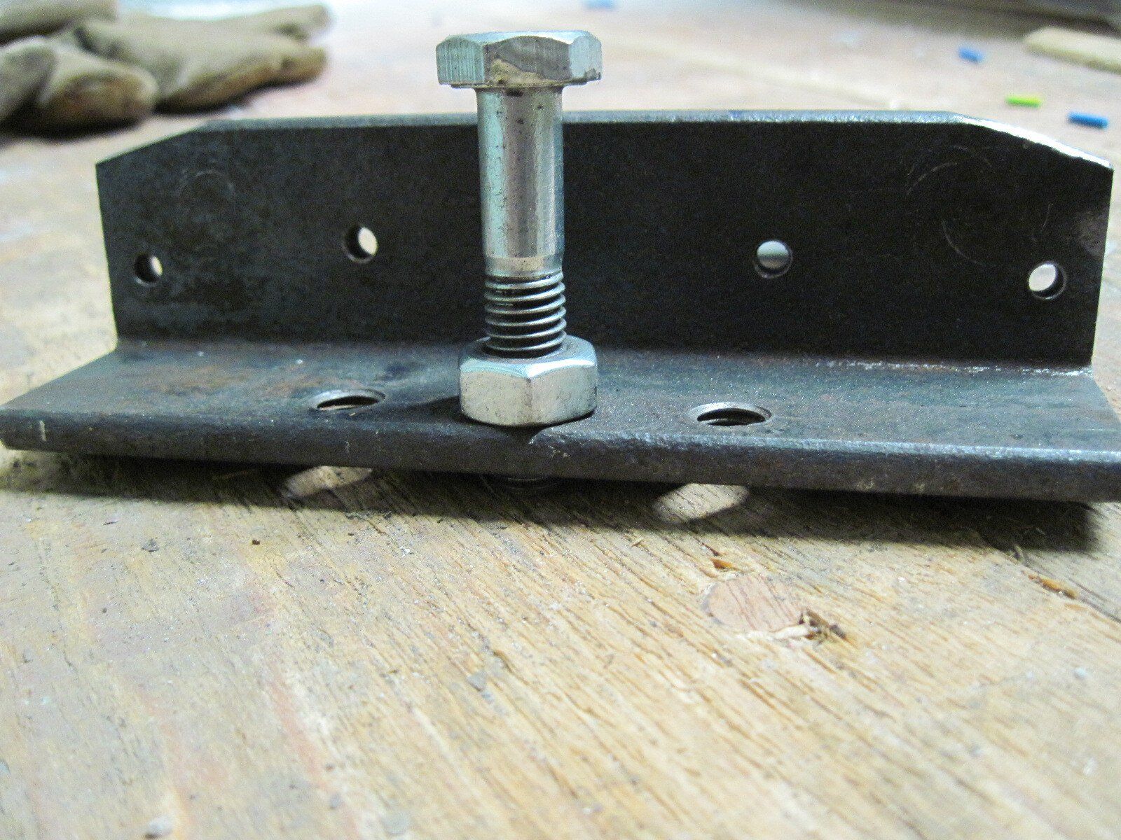
Electric motor: 2-3 hp electric motor, three phase, dull voltage, 2 pole foot mounted. Three phase to control the speed of the motor. Make sure it is a frame size 90, to fit in the No. (Parts F) brackets.
Phase convertor: Phase convertor to enable using three phase motor on domestic electric net, and to enable the motor to change the direction of its rotation. You will also need a box for it and two electric batten, one for on/off and direction and one for controlling the speed. It is rather beyond my understanding so you had better ask an electronic engineer for advice.
Main tension spring: Wire dia 3.5 or 4mm. Free length 127mm or thereabout.
Spring platform: It proved to be a difficult thing to find. However it needed to be of a size that matched the diameter of the spring. You need to find one for the top and one for the bottom. I had to improvise the kit (see in next post) and it worked. I used M8 High Knurled Nut.
2x Tracking adjustment knob: I used M8 Five Lobe Grips with External Thread. One is for the tracking idler and one for adjusting the platen.
Clamp lever: M10 clamping lever for locking the main tool arm.
M8 Cylindrical revolving grip handle: For the tracking arm.
Nuts and bolt that you need:
Length is approximate and not absolute.
For the bearings: 2x M10 Hexagon Head Setscrews 96mm + 4x Hex Nuts, + 4x Washers, 4x Spring Washers.
For the tracking hinge arm: 1x M10 Hexagon Head Setscrews 60mm + 4x Washers, + 1x Hex Nyloc Nut.
For the tracking hinge: 2x M6 Hexagon Head Setscrews bolt 28mm + 2x Washers.
For the tension spring: 1x M8 55mm Threaded Rod + 1x Washer, + 1x Hex Nut. 1x M8 Hexagon Head Setscrews bolt 60mm + 1x Washer, + 1x Hex Nut.
For the platen: 1x M12 Hexagon Head Setscrews bolt 72mm + 1x Washer, + 1x Hex Nut. 2x M10 Hexagon Head Setscrews 90mm + 2x Hex Nyloc Nuts, + 4x Hex Nuts, + 6x Washers, 2x Spring Washers. + 6x M6 Socket Head Countersunk Screws 25mm.
For the platen rollers and the idler: 3x M10 Metric Socket Head Cap / Allen Screws 90mm.
For the rest table: 2x M6 Socket Head Countersunk Screws 20mm. 2x M8 Hexagon Head Setscrews 30mm + 2x Washers, + 2x Spring Washers.
For the motor: 1x M10 65mm Threaded Rod + 2x Washer, + 3x Hex Nut. 1x 12mm dia axle rod, both end threaded 245mm, + 2x Washer, + 2x Hex Nut. 4x Hexagon Head Setscrews 96mm + 4x Hex Nuts, + 4x Washers, 4x Spring Washers, to suit the motor base.
In the next few posts I will talk about the construction and commissioning of the belt sander. So if interested, do follow by subscribing to my blog.
For people in the UK I will publish the name of a company that can source all of the above in future posts.
Have fun.
Nuts and bolt that you need:
Nuts and bolt that you need:
Length is approximate and not absolute.
For the bearings: 2x M10 Hexagon Head Setscrews 96mm + 4x Hex Nuts, + 4x Washers, 4x Spring Washers.
For the tracking hinge arm: 1x M10 Hexagon Head Setscrews 60mm + 4x Washers, + 1x Hex Nyloc Nut.
For the tracking hinge: 2x M6 Hexagon Head Setscrews bolt 28mm + 2x Washers.
For the tension spring: 1x M8 55mm Threaded Rod + 1x Washer, + 1x Hex Nut. 1x M8 Hexagon Head Setscrews bolt 60mm + 1x Washer, + 1x Hex Nut.
For the platen: 1x M12 Hexagon Head Setscrews bolt 72mm + 1x Washer, + 1x Hex Nut. 2x M10 Hexagon Head Setscrews 90mm + 2x Hex Nyloc Nuts, + 4x Hex Nuts, + 6x Washers, 2x Spring Washers. + 6x M6 Socket Head Countersunk Screws 25mm.
For the platen rollers and the idler: 3x M10 Metric Socket Head Cap / Allen Screws 90mm.
For the rest table: 2x M6 Socket Head Countersunk Screws 20mm. 2x M8 Hexagon Head Setscrews 30mm + 2x Washers, + 2x Spring Washers.
For the motor: 1x M10 65mm Threaded Rod + 2x Washer, + 3x Hex Nut. 1x 12mm dia axle rod, both end threaded 245mm, + 2x Washer, + 2x Hex Nut. 4x Hexagon Head Setscrews 96mm + 4x Hex Nuts, + 4x Washers, 4x Spring Washers, to suit the motor base.
In the next few posts I will talk about the construction and commissioning of the belt sander. So if interested, do follow by subscribing to my blog.
For people in the UK I will publish the name of a company that can source all of the above in future posts.
Have fun.