Construction of the machine.
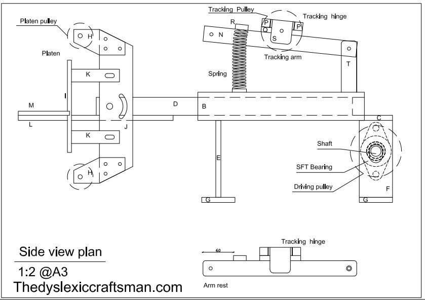
As I mention in the last post, I cut all the steel (engineer’s grade mild steel) items using laser cutting specialist.
To save money I add to use two pieces of steel for the tool arm(Parts D), but I recommend to use one piece. It is very important for the arm tool to be dead straight.
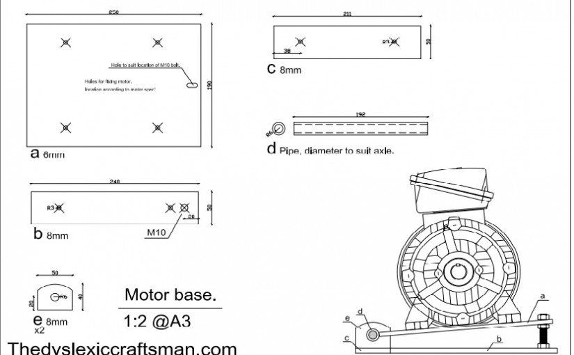
Prior to welding you want to drill all the hols and do all the threads that needed. I marked them all on the drawings. As i know myself, it is possible that I made a mistake, so please check it.
I started by well the two (Parts D) pieces together. As you will see, I am not a welder, so I add to learn how to do it from the internet. I can recommend you two web site with good instruction.
http://www.mig-welding.co.uk/learning-arc.htm
http://www.weldability-sif.com/pages/process_introductions.asp
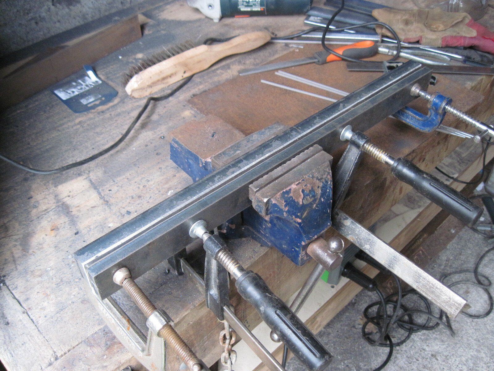
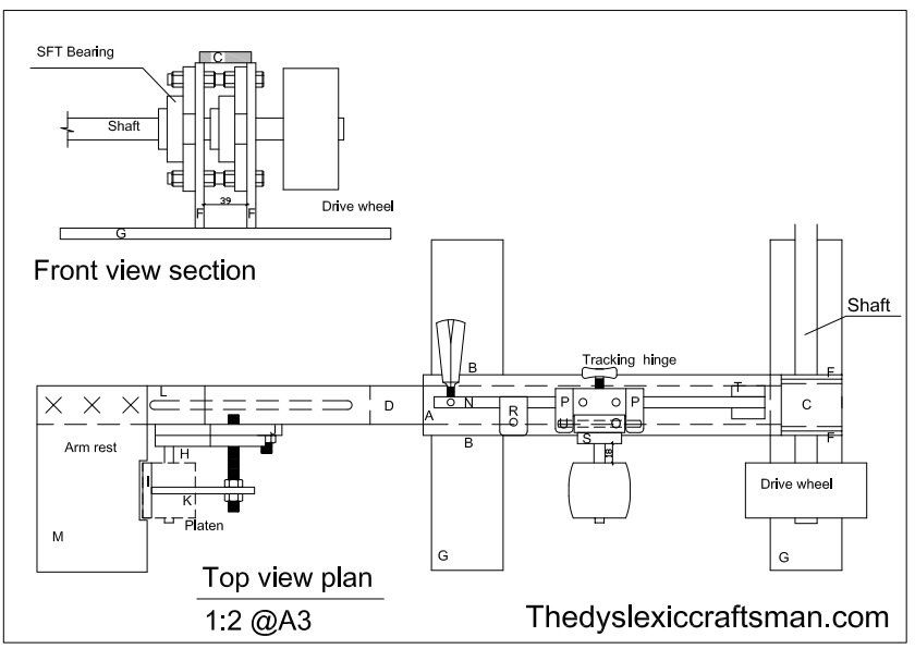
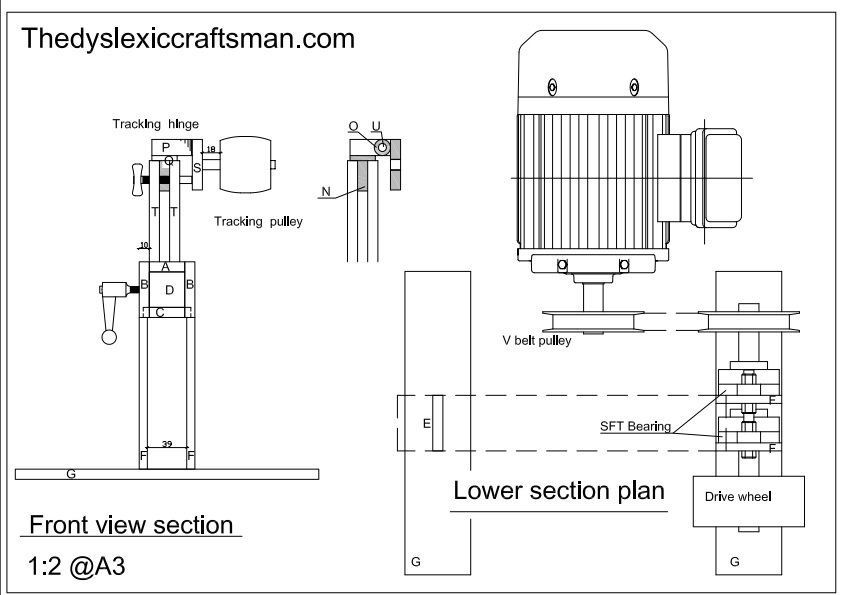
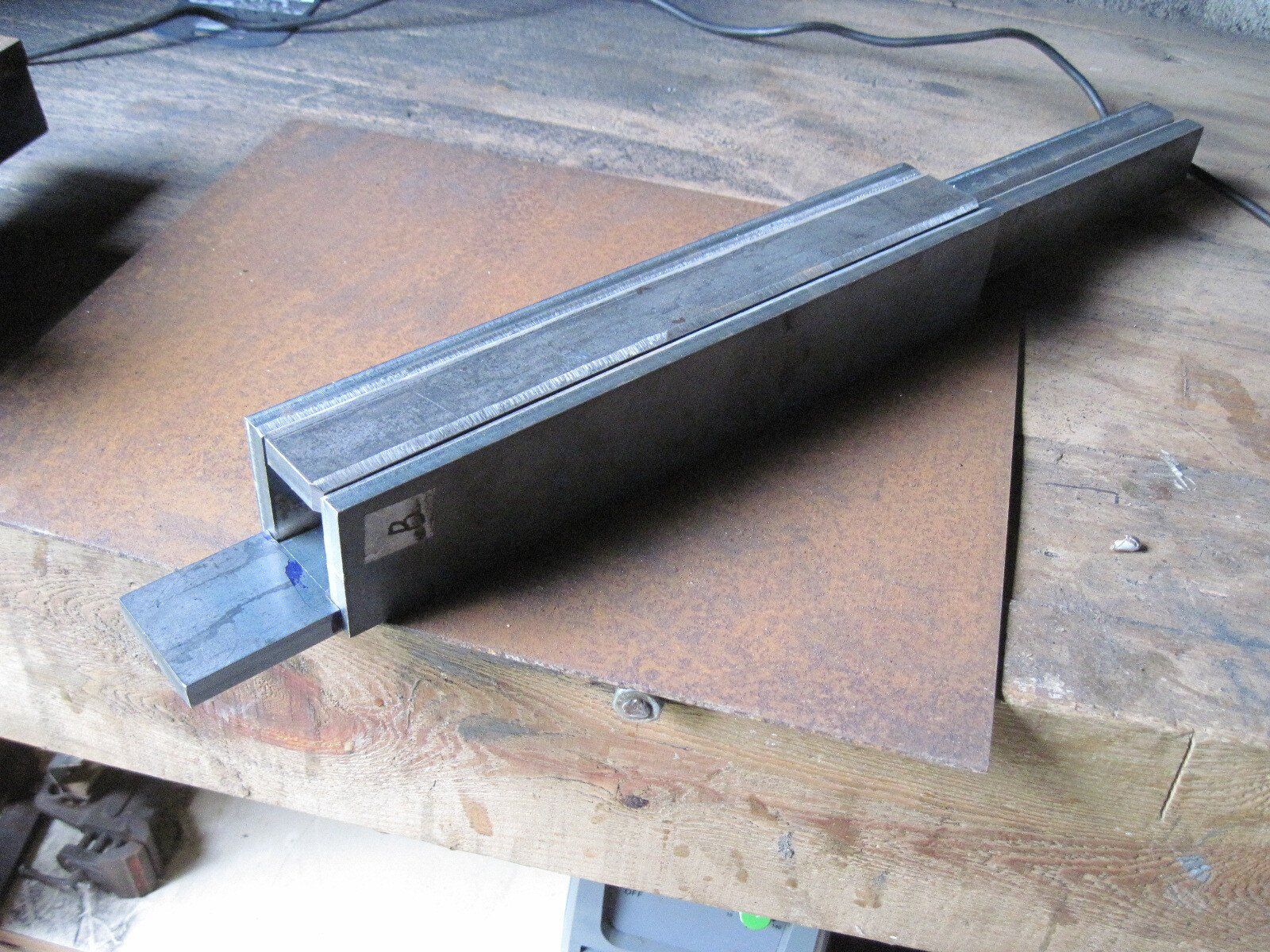
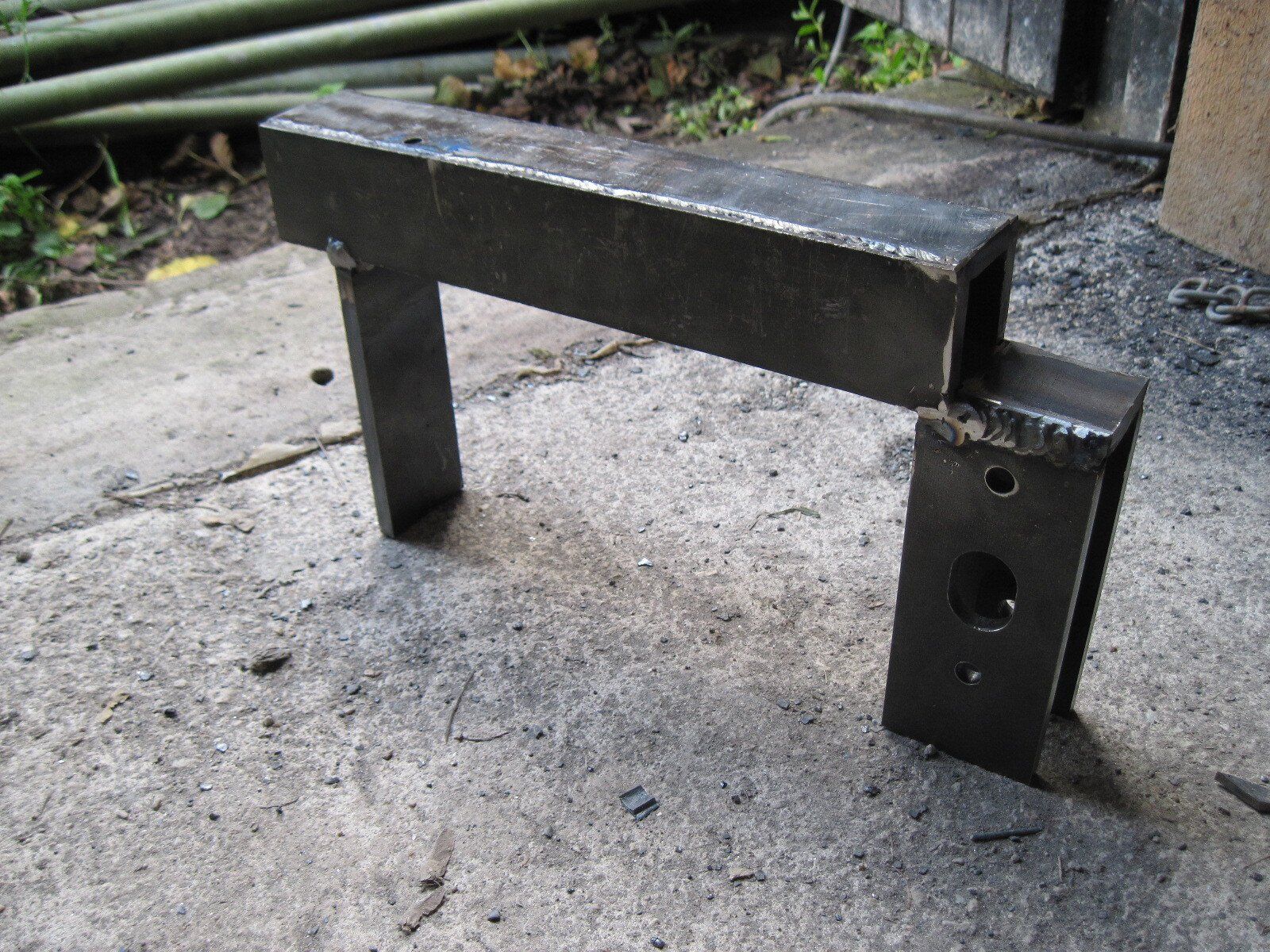
I then moved on to building the main body (parts A,B,C). Assemble all the parts around the one piece tool arm, just to make sure you will not mess with the order that you are going to weld it.
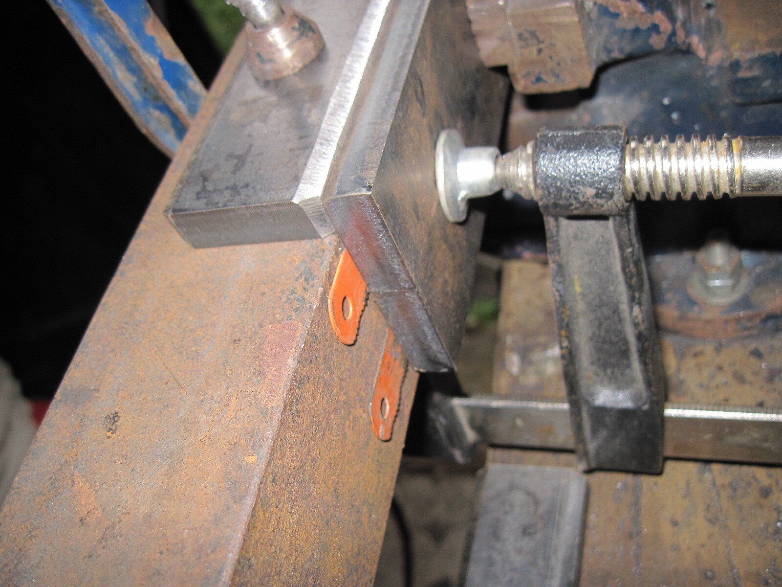
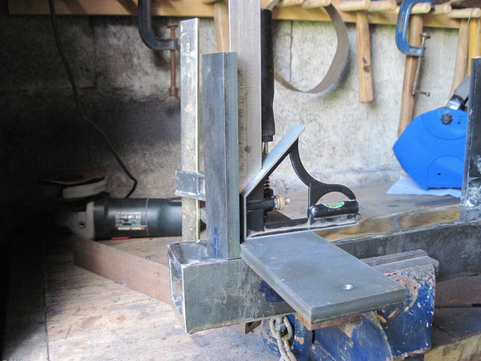
You need pay attention for two things. One is to make sure that the pieces are 90˚ to each other.
And that you need to live slight gap between the main body and the tool arm. I would say 1mm on the vertical side and one on the horizontal side. That is to enable the tool arm to slide nicely inside the main body.
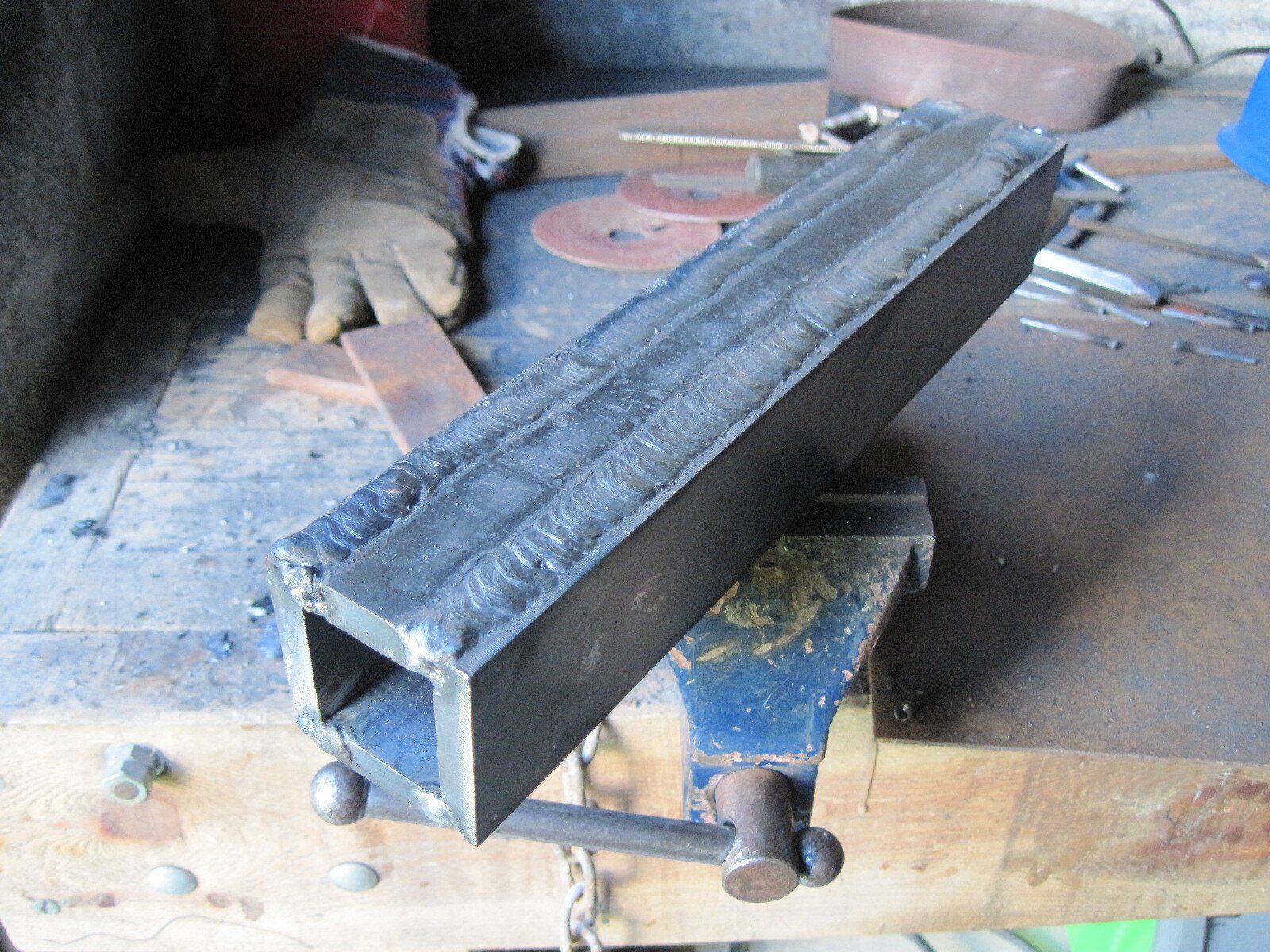
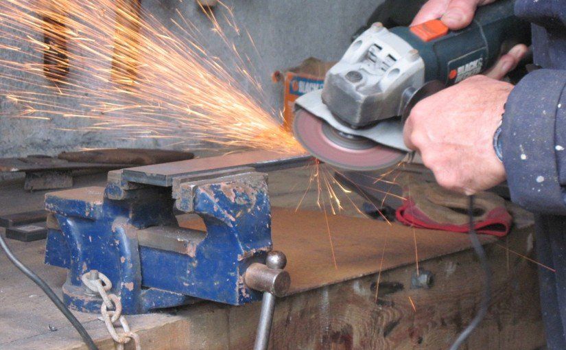
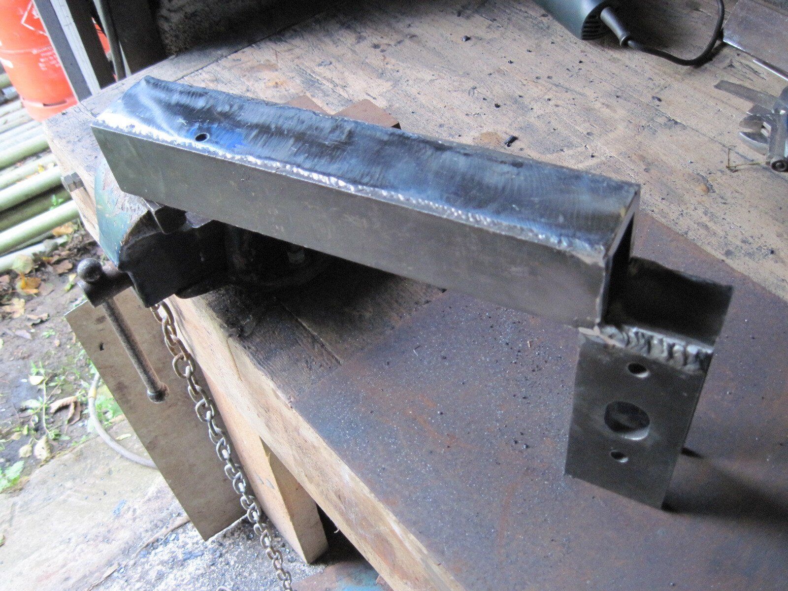
After welding you can grind the welding mark. If you do so make sure you grind it flat as possible as you still need to weld few more items on to the top side of the main body.

In hind sight you i should have assemble the part in away the well will be on the sides and not on top and bottom. That will ensure the top to be flat. If you do that you will have to change the dimension of parts A,B and C.
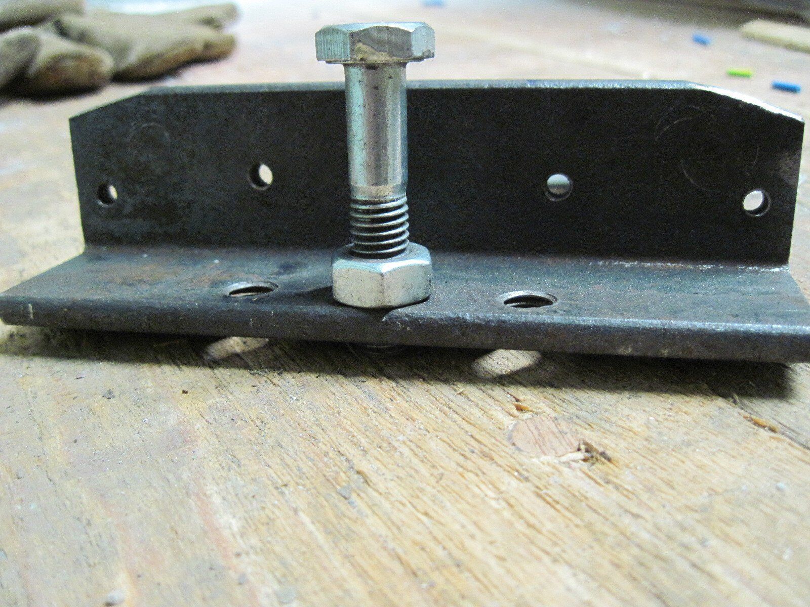
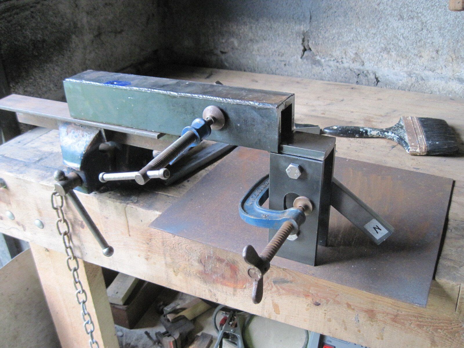
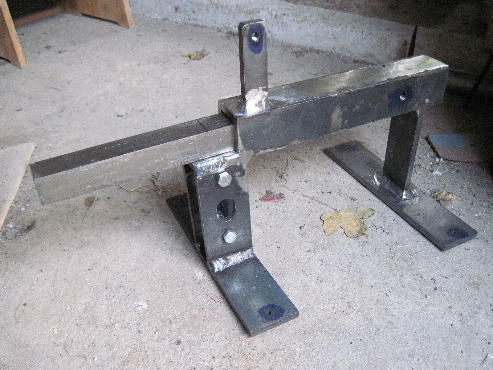
Now it time to attached bearings ‘bracket’ (parts F) to the main body.
Bolt the two F parts to achieve the exact width and make sure they are parallel to each other. Then position them in the right location under main body and make sure in is in 90 ̊to it and clump it.
You can use set square or one big lump of steel.
Now weld the front leg (Part E)
And lastly you need to attached legs base (parts G) and the leg for the tracking pulley hinge.
I advise you to mark the position of the parts by using ‘engineers marking out fluid’ as a back ground for the scribing mark. you can use heavy duty felt tip marker. It is do the job just as well and cost a lot less, and last longer.
That it. in the next post I will continue with assembling the tracking hinge and the tension spring.